Hello there!
Recently I tried to create a model replacement for a Goldsource game for the first time. I had a hard time figuring out the optimal solution, so I made this tutorial to make it public and also not forget about it in the future.
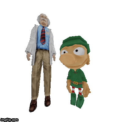
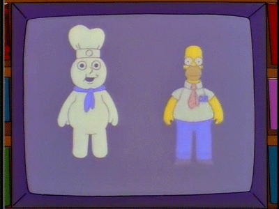
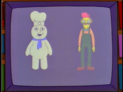
The following buddies are the two characters I was working with. The problem is, not only are they having different sizes, they also have very different proportions. This is usually a problem, because it demands a change in the skeletons bone layout, which will then again lead to outdated animations.
I will show you how I overcame this issue in Blender 2.8.
Resources you will need to follow this tutorial are the following:
- Blender 2.8
- Blender Source Tools 3.0.3
- a MDL Decompiler Tool (e.g. Crowbar or any available Model Viewer like Jed’s or Sam’s)
- a MDL Compiler Tool (e.g. studiomdl.exe which is usually found inside SDKs of Goldsource based games)
[NOTE] Wunderboy’s GUI tool and Jed’s Model Viewer are not up to date anymore and might cause trouble during compilation or decompilation!
Alternatives for compilation are direct use (drag&drop QC onto studiomdl.exe), compilation via command line application (CMD) or using Crowbar for compilation and/or decompilation.
Contents
- The two cases you may run into
- Preparations
- Case I – Same proportions
- Case II – Different proportions
- Export
- Re-compile
The two cases you may run into
Your mesh has the following properties compared to the original mesh:
- Same proportions (pay attention to Case I)
The proportions of your mesh and the target mesh are more or less exactely the same. Maybe there’s a size difference between the two, but that can be fixed by scaling your mesh up or down and then use the $scale command for re-compilation in the end, to get back your desired model size. - Different proportions (pay attention to Case II)
The proportions of your mesh and the target mesh are similar (e.g. bipedal, humanoid), but too different, to be compensated by scaling (at least without destroying your meshes proportions entirely). You will have to modify the original skeleton in a way that allows you to still make use of the original animations.
Preparations
Decompile the model you want to replace
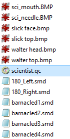
Open a MDL Viewer or another tool of your choice and use it to decompile your desired source model. Use an empty folder as export destination, as a lot of files might be created by this.
Import your custom model into Blender
Import the mesh you’re planning to replace the original mesh with, depending on the file format. If it comes in a SMD format, follow the next step (source file import).
If it comes in another format, you might want to check for a respective import addon. Otherwise try to get a OBJ format version of it, as this can be opened by any available 3D software.
If you created your model in Blender, just append its mesh from the respective blend file (yes, you should start fresh, don’t use your original working file!).
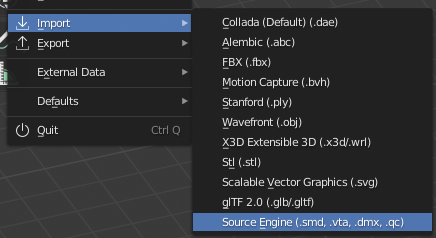
Import the previously decompiled SMD files into Blender using Blender Source Tools
While still in Blender, activate the Source Tools in the preferences and import the SMD files you just decompiled. To do this you can either just import the QC file, or select all SMD files you can find and import those. Use the following settings for this:
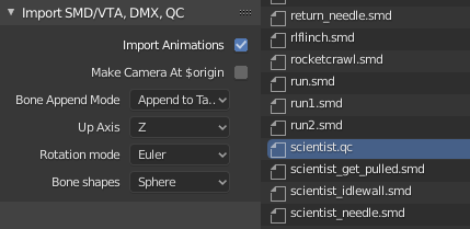
- Import Animations [check]
- Bone Append Mode [Append to Target]
- Up Axis [Z]
- Rotation mode [Euler]
- Bone shapes [Sphere]
These should be the default settings usually.
What you will end up with now, is the pure mesh and animation data of the respective model, so the Bones will have very basic shapes (spheres). For our intentions this is enough.
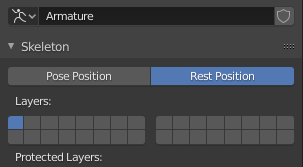
Activate the skeletons resting position before continuing!
After import there should be an armature called “skeleton” in the outliner at the right. Before you do anything else, select that armature, go to the “Object Data” tab at the right (the little green skeleton ![]() ) and select the “Rest Position” rather than the Pose position, so your armature will take a neutral pose. This is important for the further steps.
) and select the “Rest Position” rather than the Pose position, so your armature will take a neutral pose. This is important for the further steps.
Case I – Same proportions
The easiest case, as you don’t need to change any of the existing bone structure.
Special cases: mesh size or resting pose differs
Still you might need to modify your mesh, if the size differs or its pose doesn’t match the resting pose of the original mesh. Do this before you continue with the next steps. To modify your mesh, open it in edit mode and scale, move or rotate its vertices to match the reference.
Parent your mesh to the original skeleton
Now parent your mesh to the imported skeleton with an armature modifier:
- select your model and then the armature, while pressing SHIFT
- press Ctrl+P
- use “With empty Groups”
Attach your meshes vertices to the original bones
Attach your meshes vertices to the bones of the armature. The necessary vertex groups to do this should already exist IF you chose “Empty Groups” in the last step.
- select your model
- go into edit mode (press Tab)
- go to the vertices Object Data tab at the right (
 )
) - select some vertices, look for the respective bonename in the “Vertex Group” list at the right and click “Assign” to attach the selected vertices to that bone.
Check bone attachments in pose mode
From time to time you should select the armature and go into Pose Mode, so you can move and rotate the bones a bit to check the connections between bones and vertices.
Case II – Different proportions
This is a little trickier than just attaching your new mesh to the original armature, but in the end, it will probably work out, if you manage to find the right workarounds.
Also as I won’t write the similar steps twice, you will have to switch between Case I and Case II during the process.
Be aware that the steps which are necessary to make this work will ultimately change the original bone positions, so in the end you not only need to export the new reference SMD, but also the updated animation SMDs, since the skeletons bone locations and rotations will be different in the end.
Adjusting the scale
If you are able to achieve a big improvement between your mesh and the original skeletons layout by scaling the skeleton, you may do this carefully at this time. You can do it nonuniform (X, Y and Z scale can be different). When done, apply the scale to the skeleton permanently by pressing CTRL+A and SCALE while having it selected.
Adjusting the original skeletons bone locations to fit the different proportions
You can now adjust the positions (and !ONLY! the positions) of the skeletons bones to match your meshes individual proportions. You can do this in edit mode. Pay attention to only change the location, not the bone roll, scale, name or rotation!
Check Case I for further info
When you’re done with the skeleton so far, you can now attach your mesh to it. On info how to do this, look at Case I “Parent your mesh to the original skeleton”.
Adding new bones
Because this way of replacing a model already made it necessary to update and re-export all animations, you can as well add your own bones to the skeleton now, as long as they won’t break the original bone chain!
Be aware though, that this will make it necessary to care for these bones in certain animations! This might lead to a lot more work in the end, even or especially when using bone constraints and -physics. Without new bones the animations still don’t need to be touched individually to make this all work!
Adding bone constraints to correct animation issues
Now especially when replacing big models with smaller ones, you will come across the issue of faulty looking animation in terms of X/Y/Z movement, which depends on the Bip01 root bone usually.
This is because the animations were of course recorded for a mesh with a different size. While bone rotations still might look fine, the root bones location on the XYZ axes for instance, that also defines the movement in the engine in many cases (e.g. walk and run animations), might be a problem.
To compensate this for all animations at the same time, you can add bone constraints, that take away movement on those axes by a certain degree.
Of course you can also limit the rotation on certian bones.
In Blender you would do this by adding bone constraints to the respective bones:
- Select a bone while in pose mode
- Go to object constraint tab
 at the right properties area
 - To limit the bone location add a “Limit Location” Constraint to it and try some different values of Influence until you get the right result. Also choose an axis to limit. It might be necessary to add more than 1 location limiter, because you want different influences on each axis.
Leave the distance at 0 for the min and max value.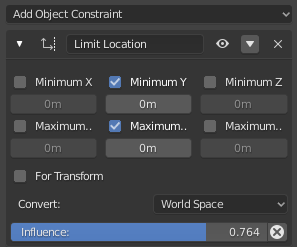
- If you want to limit bone rotations, do the same with a “Limit Rotation” constraint of course.
By doing this you can effectively modify the skeletons behaviour in all the original animations. No additional work is required this way.
Export
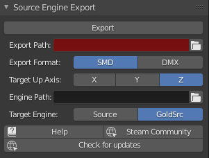
Go to the scene tab at the right and look for the BST settings. Set them up like this:
- Export Path [the folder where your SMDs shall be exported to]
- Export Format [SMD]
- Target Up Axis [Z]
- Engine [Goldsource]
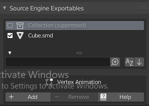
- Source Engine Exportables:
– select “Collection” and suppress it in the Group Properties area - select your custom mesh
- press Export (at the top)
You’ve now exported your custom mesh. In case everything worked, you should end up with a reference SMD file that contains your mesh data (triangles and UV coordinates) and the exact same bone list as the original model. You should check this by comparing the original SMD files with your newly exported ones.
Re-compile
You can likely use the original QC file to recompile the new version of the model. If you chose a different name for the reference SMD, you will need to modify it though:
- open the QC file in a text editor
- look for a line similar to the following one
$body "studio" "dc_sci_(headless_body)"
- change the content between the two last quotation marks to your newly exported SMD file name without the *.smd file extension
$body "studio" "MyMeshFile"
In the case of custom textures
When your model uses custom textures, you should of course include those to your working folder as well, as it would lead to a compilation error otherwise.
Compilation by dropping QC onto studiomdl
To compile the QC file you can just use your favorite way to do it, as there are no special requirements for this afaik.
Usually you can just drag and drop the QC file onto the studiomdl.exe, which has to be located in your working folder as well, in case you didn’t change the paths ($cd and $cdtexture) inside the QC file.
This method has a disadvantage, because you will not see any errors that might come up during the process. This is why it is sometimes necessary to run the process via a command line application or a tool like Crowbar or Wunderboy’s GUI tool (Note: Out of date!).
Compilation via Windows CMD
On Windows open up a CMD window and do the following:
- change the directory to your current working folder by typing
cd /d C:\MyWorkingFolderPath - run the studiomdl.exe with your qc file by typing
studiomdl.exe MyQcFile.qc
Now you’re able to see any occurring errors during the compilation process.