Last updated: 2nd February 2018
1. Using the Command Console
1.1. Main Menu
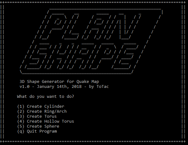
Here you can choose one of the 5 objects that Plan Shape can generate.
When loading a template file that specifies a different shape, you need to come back here to choose the wanted shape again. The loaded settings from the template file will stay.
1.2. Sub Menu
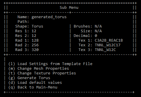
After choosing a shape you will open the sub menu. Here you also get some basic informations about the current object and settings.
1.2.1. Load Settings from Template File (l)
Type in the full path and filename+extension here, to load predefined settings from a template file.
You can also type in the filename+extension only, when the template file lies in the same directory as the PlanShape executable.
Note: If you haven’t changed any settings, you can always still generate a shape. The program will use the default settings then.
1.2.2. Automatically enlarge Model (a)
For example a coordinate before autoscale could be “78.5”, then it could be “157” when autoscale was applied. The models size was doubled, the scale factor for the editor would be “0.5”. This information will be added in the map-file and can be viewed in Hammers top menu [Map] -> [Map Properties] -> [SmartEdit] -> Keyvalues: “scalefactor”.
When a model is generated with a high resolution and a relative small size, the generated coordinates will probably contain decimal places.
When opening a map file that contains brushes with such coordinates, Hammer won’t be able to correctly calculate the corresponding planes and vertices. When you save a brush like this again in a map-file and look at it in a text editor, you will realize the coordinates are completey messed up:
Importing floating point coordinates into Hammer:
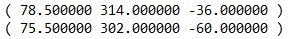
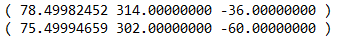
This behaviour occurs in spite of using floating point patches like the one by vluzacn. This issue can’t be adressed, so it is neccessary to enlarge said objects, before opening them in Hammer.
By sticking to the RMF format after that, you probably won’t run into trouble again.
1.3. Mesh Properties Menu
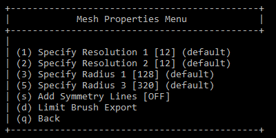
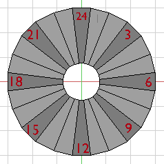
1.3.1. Resolution (1-2)
Resolutions start from 12 and are then being doubled (24, 48, 96, 192,…).
Like stated before, high resolutions are either not implemented or not tested and will probably lead to faulty results. This depends on the choosen shape, too.


1.3.2. Radius (3-5)
To avoid floating point coordinates, it is absolutely recommended to use radiuses that are at least divisible by 16, 32 or even 64.


| Cylinder | Arch | Torus | HTorus | Sphere | |
| Rad 1 | ✔ | ✔ | ✔ | ✔ | ✔ |
| Rad 2 | ✔ | ||||
| Rad 3 | ✔ | ✔ | ✔ |
1.3.3. Symmetry Lines (s)
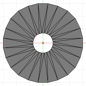
Adding symmetry lines will actually add 4 more brushes to the given object, or in other words: it will split the 4 axis-brushes into halves.


This feature doesn’t work on Cylinder, Torus and Sphere at all or only on certain axes, since the body sections of these shapes consist of single large brushes instead of many small ones.
1.3.4. Limit Brush Export (d)
Here you can specify which part(s) of the generated object you actually want to export. This can be useful when using high resolutions, which will produce a high amount of brushes.

1.3.5. Triangulate (t)
This works for the Arch shape only at the moment. It will do exactely this. Be aware that this will double the amount of brushes.
1.4. Export Rules Menu
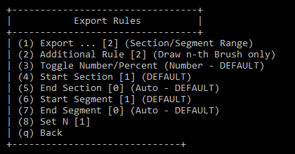
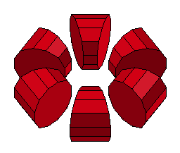
1.4.1. Export Rule (1)
The export rules apply to any shape individually. While an arch always consists of one section and e.g. 12 segments/brushes, a Torus has possibly 12 brushes/sections altogether, and only 1 segment per section/brush. This depends on how a specific shape is being constucted.
[0] (All Brushes – DEFAULT)
[1] (Brush Range)
[2] (Section/Segment Range)
1.4.2. Additional Export Rule (2)
[1] (Random)
[2] (Draw n-th Brush only)
The additional rule #2-4 uses this number to draw (export) only the nth (2nd, 3rd, 5th, …) element of the generated shape.
[3] (Draw n-th Section only)
[4] (Draw n-th Segment only)

1.4.3. Toggle Number/Percent (3)
The given numbers will be interpreted as percentage values except the N-number.
1.4.4. Start/End Brush/Section/Segment (4-7)
You can specify the start and end positions for the correspondent element (brush, section, segment) as integer number ranging from first to last element (e.g. 1-12 or 1-16 when symmetry is activated) or percentage value (0-100).
1.4.5. Set N (8)
“N” is the number used of some of the additional export rules, where only the N-th (e.g. 2nd, fourth or twelfth) element of a region (brush, section, segment) is being drawn.
N will not be interpreted as percentage value!
1.5. Textures Menu
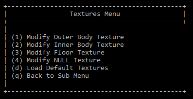
1.5.1. Modify Texture (1-4)
There are 1 to 3 texture regions, depending on the shape you’re using. 1 and 2 are usually the outer and inner sides of a shape, while region 3 is always the “floor” texture.
Floor textures have a slightly different behaviour, but act more or less the same as the body textures and use the same commands.
The Null texture region could be another region to be modified by the user, but it is not included yet. This might be the case in a future update.
1.6. Texture Properties Menu
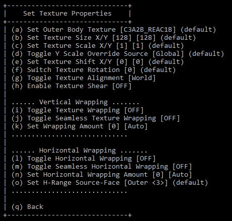
1.6.1. Set Outer/Inner/Floor Texture (a)
Use the texture name from the WAD file here. This can be a string.
1.6.2. Set Texture Size X/Y (b)
The texture pixel width and height from the WAD Bmp file. Always an integer number.
1.6.3. Set Texture Scale X/Y (c)
The basic Texture Scale can be an integer or floting point number.
1.6.4. Toggle Alternative Scale Source (d)
This defines an alternative source for the Y OR X axis scale (depends on the texture region you’re using it on) and will thus override the basic scale. The difference is, that the alternative scale is already adjusted to the model size and thus will give you a better result, without additional work. A good choice would be “[1] Match X”.
Example: Instead of having 2 different axis scales, let’s say 2.05X and 2.65Y, the Y scale will match the X scale, so both axis will have a scale of 2.05. The axis that gets the new value can’t be choosen yet. It will always be the same axis. For body regions (inner and outer faces) it will be the Y-Scale (or horizontal/long range), for floor faces the X-Scale.
1.6.5. Set Texture Shift X/Y (e)
This is the shift, that will be added on top of the final shift, when everything is done. With this you can fix little differences between texture regions or just compensate a missing symmetry line.
1.6.6. Switch Texture Rotation (f)
This rotation is added to a texture region, when everything else is done. You can only use 0, 90, 180 and 270, any other value will be ignored.
1.6.7. Toggle Texture Alignment (g)


This will toggle between world and face align for a texture region, which does exactely the same as in any Quakemap-editor only that this will always be more accurat for faces that are oriented up- or downwards. The 2 texture vectors are being aligned by using the face itself as the source.
1.6.8. Enable Texture Shear (h)


One of the most interesting features of PlanShape is the texture “Shearing”. This method will align the texture vectors at the respective face edges. Currently these edges are fixed, so you won’t be able to choose between the left or the right one.
Shearing or “Mesh Align” will produce much better results on Torus, Sphere and any floor textures, where normal face align would lead to cropped details.
Note: Currently horizontal wrapping won’t work for sheared texture regions, so the Y-axis of one torus section will always be aligned to the right edge. Also the edge can’t be chosen atm, it will always be the right one. To get different results, you can mirror the textures scale by making it negative (Y-Scale [2.0] becomes [-2.0]).
1.6.9. Toggle V/H Texture Wrapping (i/l)
This will lead to the texture of a region to be wrapped around it, based on the current scales and bmp-sizes. Unless “Seamless” is also activated, the resulting Scales will be “clean” and there will be a gap at the beginning/end point, where the texture meets itself again.
1.6.10. Toggle V/H Seamless Texture Wrapping (j/m)
While Wrapping AND Seamless are activated, this will lead to a seamless result on the respective axis.
1.6.11. Set V/H Wrapping Amount (k/n)
Any integer value greater than Zero will cause the texture to be wrapped around the shape exactely this many times.
Usually you want to leave this at “0”, but sometimes you want to have more control over how many times the texture is being wrapped around the shape. This will of course override any of the set scales and also depends on “seamless” being activated.
Zero means it will be wrapped seamless automatically, based on the current scales and sizes. This is the easiest solution for quick results, when the amount doesn’t matter.
1.6.12. Set H-Range Source-Face (o)
One of the latest additions to the program gives you the ability to choose the edge (or face), where the horizontal (Y) shift of all faces of a texture region of a Torus, Sphere or Hollow Torus is being copied from, to allow for a clean, seamless wrapping result.
This is neccessary, when you want a specific part of the shape to be more “seamless” than the others, maybe for displaying text or other details.


2. Using template files
2.1. Basics
2.1.1. *.PST Files
PST (Plan Shape Template) are simple text files. You can open end edit them with any text editor. You can also bind them to the PlanShape EXE to build them instantly even easier.
2.1.2. Comments
Comments can be added by using “//” at the end of a line or in front of it. This way commands can be commented out and will thus be ignored at the import process.
2.1.3. Placeholders
Placeholders should be spaces or tabulators.
2.1.4. Value Types
Only use the allowed data types for the respective commands.
2.1.5. Duplicates
The same command can be pasted multiple times, but will only be detected once!
2.2. Command Reference
| Command | Type | Description | Example |
| filename | string | Just the name of the final file without extensions or anything. | MyTorus_test |
| filepath | string | Leave empty when in same dir as EXE or insert full path like. | C:\Directory\blabla\ |
| exmap | bool (0/1) | Wether or not the generated object gets exported as MAP file. | 1 |
| exobj | bool (0/1) | Wether or not the generated object gets exported as OBJ file. | 0 |
| nomenu | bool (0/1) | For drag and drop operations (drag and drop a template file onto the PlanShape-EXE to generate it). IF you just want to load the template file after D&D and still be able to modify some settings, leave this at 0. |
|
| autoscale | bool (0/1) | Wether or not the model gets enlarged automatically before being saved as MAP file. | 1 |
| shape | string | Which shape shall be generated. Use one of the following: cylinder, arch, torus, htorus, sphere | cylinder |
| #Basic Mesh Information# | |||
| res | integer | Resolution 1 (valid for all shapes). Only use doubled version of 12: 12, 24, 48, 96, … | 12 |
| res2 | integer | Resolution 2 (needed for Torus and Hollow Torus only) | 24 |
| rad | integer | Radius 1, applies to all shapes. | 512 |
| rad2 | integer | Radius 2, applies to Hollow Torus only. Must be bigger than HALF the distance between Rad 1 and 3! | 960 |
| rad3 | integer | Radius 3, applies to Arch, Torus and HTorus. | 1024 |
| sym | bool (0/1) | Add symmetry lines. | 0 |
| tri | bool (0/1) | Add triangles. Currently only works on the Arch. | 0 |
| #Export Rules# | |||
| rule1 | integer | [0] (All Brushes – DEFAULT) [1] (Brush Range) [2] (Section/Segment Range) [Dependencies] The following commands need this to work: start1, start2, end1, end2 |
2 |
| rule2 | integer | [0] (None – DEFAULT) [1] (Random) [2] (Draw n-th Brush only) [3] (Draw n-th Section only) [4] (Draw n-th Segment only) [Dependencies] The following commands need this to work: nth |
3 |
| percent | bool (0/1) | When activated, the ranges stated below (e.g. start1, end1) are interpreted as percentage values. | 1 |
| nth | integer | The second rule #2-4 uses this number to draw (export) only the nth (2nd, 3rd, 5th, …) element of the generated shape. | 3 |
| start1 | integer | Start/End element. This uses the total amount as maximum and the least one as minimum. For a resolution of 12 this would be “1” for start- and “12” for the end command. |
4 |
| end1 | integer | ^ | 9 |
| start2 | integer | ^ | |
| end2 | integer | ^ | |
| #Texture Region 1-3 Settings# | |||
| n_tex | string | Null texture (name from WAD file) | solidhint |
| 1_tex | string | Texture name from WAD file | C1A0_LABW3 |
| 1_sizex | integer | Texture size X (from BMP file) | 128 |
| 1_sizey | integer | Texture size Y (from BMP file) | 96 |
| 1_shiftx | floating point | X/Y axis shift, that is being added on top of the final shift. | 24.2452 |
| 1_shifty | floating point | ^ | 155 |
| 1_scalex | floating point | Basic X/Y scale, you wanna use on this axis. This will get overridden by the wrapping amount command for seamless texture wrapping. | 2.75 |
| 1_scaley | floating point | ^ | 3.5 |
| 1_scalesrc | integer | Scale-source for a certain texture-axis. The scale will be copied from the final scale of another axis. This applies to the Y axis of Cylinders, Arches, Tori and the Sphere. Floor faces have a different axis layout, so it will be the X axis there. [0] (Global – DEFAULT) [1] (Match X Scale) [2] (Round X Scale) [3] (Custom) |
2 |
| 1_rot | integer | Rotation that gets added on top of the final texture. Can be 0, 90, 180 and 270 only! | 270 |
| 1_facealign | bool (0/1) | Turn on facealign for this texture region. [Dependencies] The following commands need this to work: shear, v_wrap, h_wrap |
1 |
| 1_shear | bool (0/1) | Turn on shear (mesh align) for this texture region. | 0 |
| 1_v_wrap | bool (0/1) | Turn on wrapping for this texture regions vertical axis. [Dependencies] The following commands need this to work: v_seamless |
1 |
| 1_v_seamless | bool (0/1) | Turn on seamless wrapping for this texture regions vertical axis. [Dependencies] The following commands need this to work: v_wrapam |
1 |
| 1_v_wrapam | integer | The amount of times the texture is being wrapped around the texture region seamlessly. “0” means the texture will be wrapped automatically, based on its scale and size. [0] (Auto – DEFAULT) [X] (Custom Amount) |
5 |
| 1_h_wrap | bool (0/1) | Horizontal wrapping… (see above) | 1 |
| 1_h_seamless | bool (0/1) | Horizontal seamless wrapping… (see above) | 1 |
| 1_h_wrapam | integer | Horizontal wrapping amount… (see above) | 0 |
| 1_h_rangesrc | integer | This will change the source edge for the horizontal shift calculation to another edge. [0] (Outer – DEFAULT) [1] (Lower) [2] (Inner) [3] (Upper) [4] (Custom) [Dependencies] The following commands need this to work: h_range |
4 |
| 1_h_range | integer | The custom edge-number for the horizontal Shift calculation can range from the smallest element number “1” to the biggest, e.g. “12” (24,48,…). | 9 |
3. How Textures work
3.1. Texture Regions
| Cylinder | Arch | Torus | HTorus | Sphere | |
| Tex 1 | ✔ | ✔ | ✔ | ✔ | ✔ |
| Tex 2 | ✔ | ✔ | |||
| Tex 3 | ✔ | ✔ | |||
| NULL | ✔ | ✔ | ✔ | ✔ | ✔ |


3.2. Texture Align
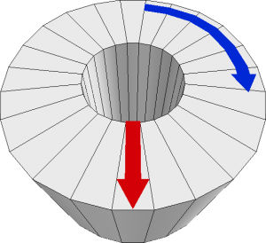
Heritage
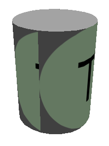
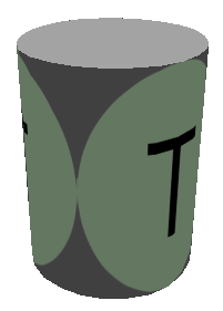
Notice that the Torus is only a group of cylinders, stringed together in a horizontal orientation.
A hollow Torus therefor, is the same, just made of multiple Archs.
The Sphere again, is being treaded almost like a normal Torus by the texturing-function.
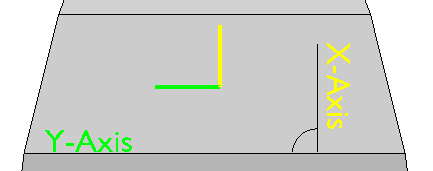
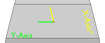
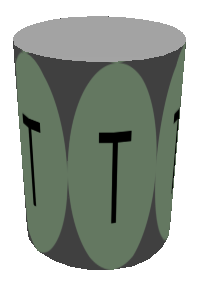
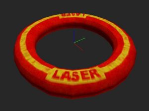
During the process all texture regions in PlanShape are usually be treaded as in Hammer, meaning they will have the same orientation and rotations. Up is up, and left ist left.
One exception is, that you need to think of the Tori and the Sphere as tilted chains of Cylinders or Arches, so the texture orientation is tilted, too, namely 90 degree counterclockwise.
Note: The wrapping axes (horizontal and vertical) are not influenced by the rotation. The texture rotation only changes the faces texture-vectors. Shifts and Scales stay the same and don’t have to be adjusted manually by the user!


3.3. Texture Wrapping
There are 2 wrapping axes in PlanShape, that are important to understand, the horizontal and the vertical. They change, depending on the object you want to create and the texture region you’re adjusting.
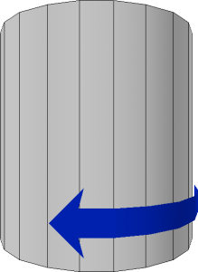
Cylinder and Arch
Cylinders and Arches only feature a vertical wrapping axis.
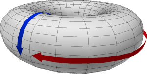
Tori and Sphere
Tori and Spheres feature both axes to wrap the texture completely seamlessly around the shape.
Floors
The axes for floors are maybe a bit confusing. Try to remember this image and you should be fine.