Contents
- Splines (formerly “paths”)
- New Curve Type: “Intersecting Spline”
- New spline related commands
- Toggle curve brushes with c_enable
- Texmode to control texture mapping
- Heightmode for controlling height distribution
- Toggle map export
- Detail Objects work for all curve types now
- Ramp command changed
- Complete Changelog of v0.6
Splines (formerly “paths”)
“Paths” are now called “Splines”.
To include a spline into your curve project, use the splinefile command (formerly path).
The only valid spline input type are paths stored in map files, which were created using the path tool in a Goldsource editor. The knot type must be path_corner.
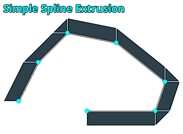
Splines can be used with type 2 (simple spline extrusion) and type 3 (intersecting spline extrusion).
To also use the height information of a spline, use the new command heightmode 2 furthermore.
New Curve Type: “Intersecting Spline Extrusion”
This new curve type works by intersection of edges (spline segments), but just like for the so far available simple spline extrusion method, you can use your very own spline as a base for it.
rad 0
type 3 //curve type “intersecting spline extrusion”
heightmode 2 //height information in spline file is being used”
Unlike the simple spline extrusion, the results can be a lot smoother and more natural looking, but will therefor end up in floating point coordinates and potential compiling glitches like holes and ugly VIS cutting more likely, so using it with discretion is crucial.
Once more it is advised to always use the “SOLIDHINT” texture for any brushface, that won’t get rendered!
New spline related commands
To be able to better control splines without having to edit the original splinefile, I added several new commands:
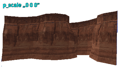
p_scale for simple scaling
Scales the original spline (loaded with splinefile) on the individual axes (XYZ) based on the splines center.
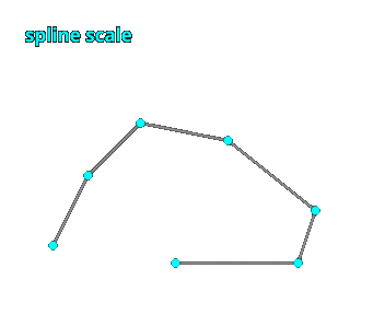
For this example to work, the original spline (a path in a map file made of path_corners) needs scalable information of course (aka differing coordinates on the relevant axis).
rad 0
type 3 //curve type “intersecting spline extrusion”
heightmode 2 //height information in spline file is being used”
p_scale “0 0 3” //spline is scaled by 3 on the Z axis
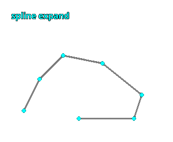
p_expand to expand based on orientation
Expands the original spline, based on the combined direction of 2 connected segments. Compared to simple scaling this can preserve the original shape but can lead to problems in other cases (e.g. notches). Has to be used with care!
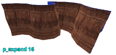
rad 0
type 3 //curve type “intersecting spline extrusion”
p_expand -128 //spline is expanded by -128 game units
p_evenout to adjust knot density
Matches the knot density of a spline based on the shortest spline segment. Can be used to easily fill very long sections in order to generate detail or smooth ramps.
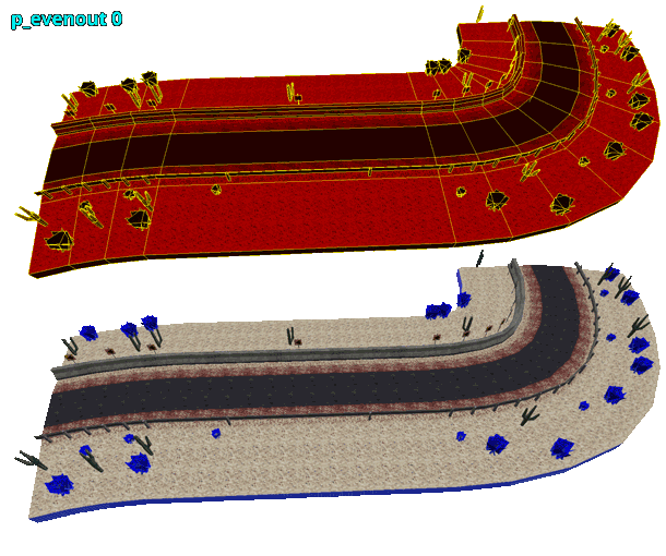
rad 0
type 3 //curve type “intersecting spline extrusion”
p_evenout 1 //automatically adjusted knot density
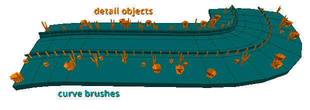
Toggle curve brushes with c_enable
Analog to enabling and disabling detail objects (d_enable), you can now as well toggle curve brushes with c_enable, which can be useful to skip curve brushes and only export detail objects or the other way around.
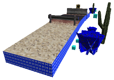
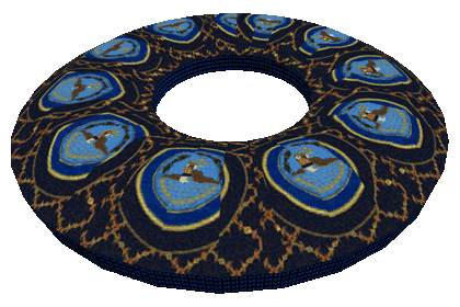
This example shows how to use the original knot density of a spline for the mesh of a curve, and the increased knot density for the detail objects:
What is going on here? There’s a very long section in the underlying spline, which you naturally want to use for the curves mesh, as it uses a much smaller amount of world polygons like that.
You still want to have a well-balanced density for the detail objects though, like in the picture. To do this, you can now create 2 curve objects and use p_evenout 1 on the one, that is used to generate the detail objects. Then you just disable the mesh for that curve using c_enable 0 and voila.
rad 0
rad 0
type 3 //curve type “intersecting spline extrusion”
c_enable 1 //curve brushes enabled
c_enable 0 //disabled
d_enable 0 //detail objects disabled
d_enable 1 //enabled
p_evenout 0 //original knot density
p_evenout 1 //and increased
Texmode to control texture mapping (square/seamless)

Until now the only way textures could be mapped onto brush faces in Map2Curve was very simple (square) and didn’t respect the conical distortion of the curves sections.
I always wanted to add a way to make curve textures more seamless, so I added it for Pi and Grid circle types (type 0 and type 1) now.
If you want to use it, keep something in mind: As there are no subdivided UV maps in Goldsource, it demands for a much higher amount of brushes and thus world polygones to get very smooth looking results! This makes it only interesting for very rare situations, where it can actually add important optical quality.
Doing it manually
You might already know one way of doing it: JACKs UV lock feature. It enables you to distort faces in vertex editing mode, while also manipulating the texture vector, shift and scale of the involved faces, to maintain its original mapping.
While this works in many cases, it has to be used carefully and comes with a lot of work for more complex objects.
Doing it in Map2Curve
- use a curve
typeof 0 or 1 - use the new
texmodecommand with a value of 1 - use
tri 1to triangulate the curve brushes - using this on ramps is not supported currently!
type 0 //Pi Circle curve type
res 16 //resolution should be high enough
tri 1 //curve brushes will be triangulated
texmode 1 //textures will be mapped seamlessly
Avoid distortion issues
If used in the right situations, the optical quality of seamless textures can be very good. For this to work, use this method on brushes with fitting textures only, so low curve rsolutions are no problem after all.
Then fit the textures to the faces manually while in a Goldsource editor. JACK can fit textures proportionally (e.g. 0.5 horizontally and 2.0 vertically), which is very helpful in this situation.
Heightmode for controlling height distribution
If a curve has a height other than 0, you can now specify the way that the height is being distributed along the curves slope using the following values for the heightmode command:
- Linear Slope
- Smooth Slope
- Spline (is taken from a spline file)
- Random Jagged
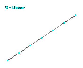
As before, the overall height results from the height command and the number of sides the spline has, which is given by the res command or the amount of spline-segments in a spline file. (e.g. height 32 * sides 8 = total height of 384)
rad 0
type 3 //curve type “intersecting spline extrusion”
ramp 1 //creates a ramp instead of stair steps
heightmode 2 //ramp will be created by using height information from spline file
Toggle map export
Wheter a curve is exported to map format or not, can now be controlled with map, which works for individual curve objects, like obj does too. This is active per default. One export format has to be active for anything to be exported, naturally.
rad 512
map 0 //Curve #1 won’t be exported to map file!
map 1
Detail Objects work for all curve types now
Detail Objects can be used in each curve type now. Until now they only worked with the Pi circle construction method (type 0).
Ramp command changed
Until now you would for instance use the height command and ramp with a value of 1 (linear ramp) or 2 (smooth ramp) to create a sloped curve. Now ramp only works for turning ramps on and off (1/0).
Complete Changelog
- Added the new curve type “intersecting spline extrusion” (3), which works very different to the simple spline type (2). It can produce much smoother and natural shapes, but will also generate floating point coordinates more likely.
- Added the following commands for spline curves:
- p_scale
- p_expand
- p_evenout
- Added command “c_enable” to toggle curve brushes, which works analog to “d_enable”, which toggles detail objects on and off.
- Added command “map” to toggle export to map format. Is active per default.
- Made Detail Objects work for all curve types! They only worked for Pi circle (0, default curve type) until now.
- Changed nomenclature of “path” to “spline” in general.
- Changed “path” command to “splinefile” to make it more distinct.
- Added “heightmode” command to control the way how height is being added to the curve sections:
- Linear Slope
- Smooth Slope
- Spline
- Random Jagged
- Made negative heights possible.
- Changed “ramp” command to be for only enabling (1) and disabling (0) ramp mode instead of toggling slope mode (1-linear/2-smooth) too.
- Changed default texture for generated faces from “NULL” to “SOLIDHINT”, which is supported by the VHLT Compilers.
- Changed bounding box texture from “NULL” to “SKIP”, which causes it to be ignored during compilation.
- Added texture shift minimizing (will be applied automatically).
- Fixed a textur shift issue with splines.